Top 20+ Current Transformer Interview Questions

current transformer interview questions

Here we are going to discuss some very important current transformer interview questions with proper answers which are mostly asked of Electrical Graduates in every industrial interview as well as in the university exam viva. So please go through all these CT interview questions with their appropriate answers to improve your subject knowledge.

What is a Transformer?

A transformer is a passive electrical device that is used to transfer Electrical Energy between two or more electrically isolated circuits. It works on the principle of electromagnetic induction. The transfer of electrical energy from one circuit to another takes place with the help of mutual induction. It is most commonly used to step up or step down the voltage of Electrical Power. It transfers the electrical power from one place to another without any variation in its frequency. It is also a static device that maintains constant flux throughout its operation.

What is an Instrument Transformer?

Instrument transformer is a type of Electrical transformers that are used for the measurement of voltage, currents, and power in AC circuits. In an Electrical power system, the level of currents and voltages are very high, therefore the direct measurement of these electrical quantities is not possible practically. In such a case, the instrument transformer is being used to step down the voltage and current within the range of the existing measuring instrument.
There are two types of instrument transformers available.
  1. Current Transformer (CT)
  2. Potential Transformer (PT)

What is a Current Transformer?

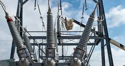
A current transformer is an instrument transformer, which is generally used to measure currents of high magnitude. It steps down the current which is to be measured so that it can be measured with an existing normal range ammeter. A Current Transformer has just one conductor or very few numbers of turns in its primary winding. The secondary winding has large numbers of turns wound according to specific turns ratio.

What are the types of Current Transformer?

According to its magnetic circuits, there are three types of current transformers commonly used in power systems. These are:
  1. Ring type CT
  2. Core type CT
  3. Shell type CT

Why Current Transformers are used for measurement?

There are mainly two reasons for using CT in measurement:
  1. To extend the range of the existing measuring instrument (Ammeter).
  2. To isolate the circuit of measuring instruments from a high-voltage line.

What is the turn ratio of the current transformer?

The turns ratio of a current transformer is NP / NS = IS / IP. A CT of turns ratio of 100:5 would mean the primary current of 100 amperes would produce a secondary current of 5 amperes in the Ammeter connected.

What is the burden on C.T.?

The burden of CT is the maximum load (in VA) that can be applied to the secondary of CT. It can be expressed in two ways. The burden is expressed as the total impedance (in ohm) of the circuit. It can also be expressed as total volt-ampere (VA) and power factor at a certain value of voltage or current and frequency.


Is the current transformer a step-up transformer?

Yes, C.T. is a step-up transformer that steps down the current up to measure the range of the ammeter. The primary of this transformer consists of one or more turns of thick wire connected in series with a high voltage line. The secondary winding consists of a large number of turns of thin conductors.

What are the basic differences between CT and PT?

These are the main differences between a Current Transformer and a Potential Transformer:
  • C.T. is connected in series with the HT line whereas P.T. is connected in parallel to the HT line.
  • In C.T, the no. of turns becomes inversely proportional to the current whereas in P.T no. if turns become directly proportional to the voltage.
  • In CT the primary has one or more turns of thick conductors and the secondary has a large no of turns of thin conductors whereas in PT the primary has a large number of turns of thin conductors and the secondary has a few number of turns of thick wires.
  • C.T. is a step-up instrument transformer that steps down the current whereas P.T. is a step-down instrument transformer that steps down the voltage up to measuring range.

Why the secondary terminal of CT should not be left open-circuited?

In a current transformer, the primary current does not depend on the secondary load of CT. It purely depends on the line current where it is connected in series. If the secondary winding of CT is kept open then the secondary current will be zero while the primary current of CT will remain the same. Therefore the opposing MMF in secondary winding will no longer exist. Hence the net MMF is due to primary current only which is very large. This large MMF will produce a huge flux in the core of CT. Hence it will saturate the core of CT. Again, due to huge flux in the core, the flux linkage of secondary winding will be large which in turn will produce a very large amount of voltage across the secondary terminal of the CT. Hence the large voltage across the secondary of CT will be very dangerous which will lead to insulation failure. There is a chance that the person who is opening the secondary winding of CT while the primary is energized will die due to electrical shock.

What is the knee point voltage of CT?

The knee point voltage of CT is defined as the amount of voltage at which a 10% increase in the secondary voltage of CT results in a 50% increase in its excitation current. The knee point indicates the saturation point of CT on the B-H curve or magnetization curve. Above the knee point voltage, the CT gets saturated. The knee point voltage is an important parameter for the selection of CT for a particular electrical installation.

How to calculate the knee point voltage of CT?

When a 10% increase in voltage gives you a 50% increase in excitation current, then that voltage is known as knee point voltage. To measure the knee point voltage, first, demagnetize the CT and then apply voltage gradually from the secondary keeping the primary winding open-circuited. While doing this, the above phenomena will be observed then that voltage is recorded as the knee point voltage of the current transformer.

What are errors in C.T.?

There are two types of errors that occur in CT. These errors are:
  1. Ratio error:- The ratio error is the amount by which the secondary current differs from the exact proportionality of the primary current of CT. It is expressed in the percentage of rated secondary current.
  2. Phase difference error:- The phase difference error is the angle by which the secondary current differs in phase from the primary current of CT. It is expressed in minutes of arc.

At what load the phase angle error of CT will be negative?

The phase angle error of the current transformer will be negative at a load of low power factor.

If the core of CT is permanently magnetized then how will you demagnetize it?

To demagnetize the core of CT, A variable resistance of high value is connected across the secondary terminal of CT, and the full rated current flowing through the primary resistance is gradually reduced to zero.

What is meant by turn compensation?

Turn compensation is the process of maintaining the no of turns one or two less than that obtained by the normal ratio. This technique is used to reduce the current ratio error in CT. 

What materials are used for the core of C.T. and why?

In order to reduce the ampere-turns (AT) needed the core of a C.T. must have high permeability, a low flux density, small iron loss, and low phase difference error. Suitable materials for the core of CT are Silicon steel which has the maximum permeability in the range of 4500 at flux densities of approx 5000 lines/cm2 with the phase difference error limited to 1.5 to 2. A nickel-iron alloy (Mu-metal) which contains a small amount of copper having a maximum permeability of 80000 at flux density near about 3500 lines/cm2 with phase difference error below 0.5is also used for the core of CT.

The nickel-iron alloy (Mu-metal) reduces the magnetizing current and core losses by up to 10% as compared to the corresponding silicon steel material. Hence Nickel-iron alloy is the most suitable material for the core of C.T. where a high degree of accuracy is required.

What is the effect of saturation on the performance of C.T.?

On reaching saturation, the transformer ratio is affected. It results in an increase of excitation current due to the reduction in magnetizing inductance and reducing a phase angle error in the C.T., which deviates primary and secondary current from their desired phase opposition i.e. 180⁰.

The increase in the excitation current of CT causes the reduction in secondary output which reduces the speed of over-current relays. The saturation of CT also disturbs the balance in differential relays thus affecting the stability of protection. Therefore the effect of saturation makes the operation of CT unsatisfactory.

Also Read:
Share with Friends

Hey, I'm Satish Gupta an Engineer by profession and blogger by passion. I am writer and founder of this blog, Here I publish contents related to Electrical and Electronics Engineering..

Leave a Comment